Japonský architektonický institut (AIJ) představil řadu známých srovnávacích scénářů simulace větru.
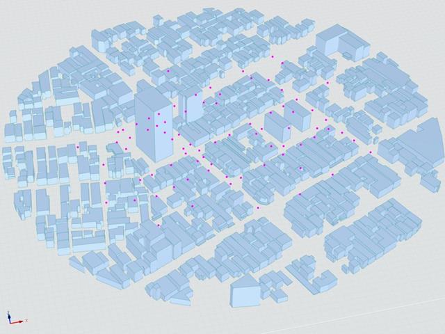
V následujícím příspěvku se budeme zabývat případem E - komplex budov ve skutečné městské oblasti s hustou koncentrací nízkopodlažních budov ve městě Niigata.
V následujícím textu je popsaný scénář simulován v programu RWIND2 a výsledky jsou porovnány se simulovanými a experimentálními výsledky AIJ.
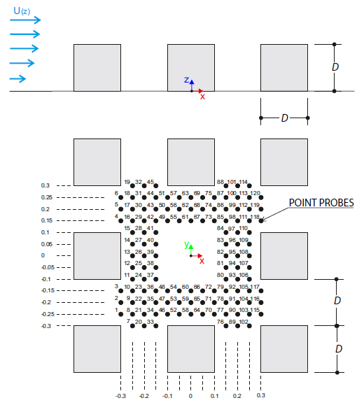
Verifikační příklad popisuje zatížení větrem v několika směrech proudění větru na modelu skupiny budov. The model consists of eight cubes. The velocity fields obtained by the RWIND simulation are compared with the measured values from the experiment. The experimental data are measured using a thermistor anemometer in the wind tunnel.
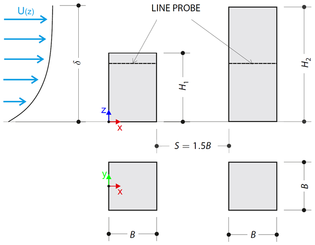
Verifikační příklad popisuje tlaková zatížení na stěny budov v tandemovém uspořádání na úrovni terénu. The buildings are simplified to rectangular objects and scaled down while maintaining the elevation ratios. The pressure distribution on the walls of the model of a medium-high building was conducted by an experiment. The chosen results (pressure coefficient Cp) are compared with the measured values.
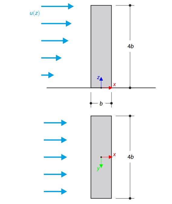
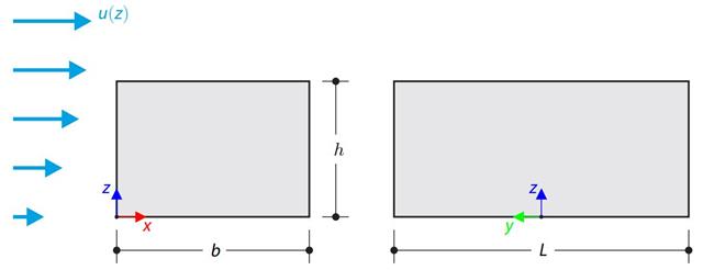
Verifikační příklad popisuje ustálené proudění okolo osamělé budovy (zmenšený model).Příklad je uveden od AIJ (Architectural Institute of Japan). The chosen results (velocity magnitude) are compared with the measured values.
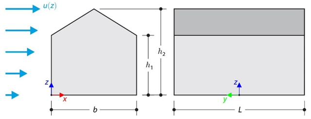
This verification example compares wind load calculations on a duopitch roof building using the ASCE 7-16 standard and using CFD simulation in RWIND Simulation. Budova je zadána v souladu s náčrtem. Rychlostní profil proudění vzduchu byl definován podle normy ASCE 7-16.
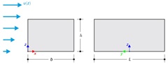
This verification example compares wind load calculations on a flat roof building using the ASCE 7-16 standard and using CFD simulation in RWIND Simulation. Budova je zadána v souladu s náčrtem. Rychlostní profil proudění vzduchu byl definován podle normy ASCE 7-16.
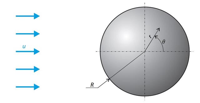
A sphere is subjected to a uniform flow of viscous fluid. The velocity of the fluid is considered at infinity. The goal is to determine the drag force. The parameters of the problem are set so that the Reynolds number is small and the radius of the sphere is also small, thus the theoretical solution can be reached - Stokes flow (G. G. Stokes 1851).
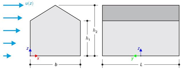
Verifikační příklad porovnává výpočet zatížení větrem na budovu se sedlovou střechou podle normy EN 1991-1-4 a pomocí CFD simulace v programu RWIND Simulation. The building is defined according to the sketch, and the inflow velocity profile is taken according to the standard EN 1991-1-4.
Verifikační příklad porovnává výpočet zatížení větrem na budovu s plochou střechou podle normy EN 1991-1-4 a pomocí CFD simulace v programu RWIND Simulation. The building is defined according to the sketch, and the inflow velocity profile is taken according to the standard EN 1991-1-4.
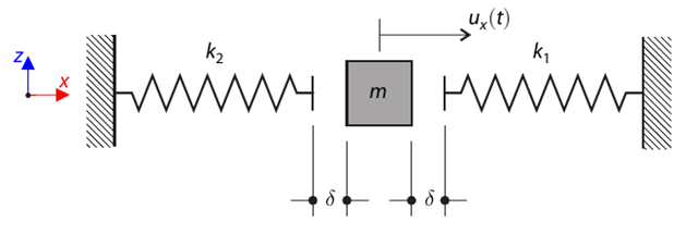
Hmotový systém s vůlí a dvěma pružinami se nejdříve vychýlí. Determine the natural oscillations of the system - deflection, velocity, and acceleration time course.
A membrane is stretched by means of isotropic prestress between two radii of two concentric cylinders not lying in a plane parallel to the vertical axis. Find the final minimum shape of the membrane - the helicoid - and determine the surface area of the resulting membrane. K tomu slouží přídavný modul RF-FORM-FINDING. Elastic deformations are neglected both in RF-FORM-FINDING and in the analytical solution; self-weight is also neglected in this example.
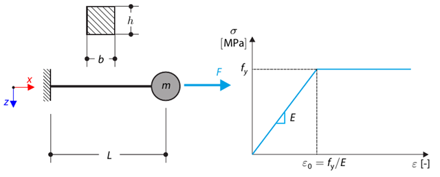
Tento verifikační příklad vychází z verifikačního příkladu 0122. A single-mass system without damping is subjected to an axial loading force. An ideal elastic-plastic material with characteristics is assumed. Determine the time course of the end-point deflection, velocity, and acceleration.
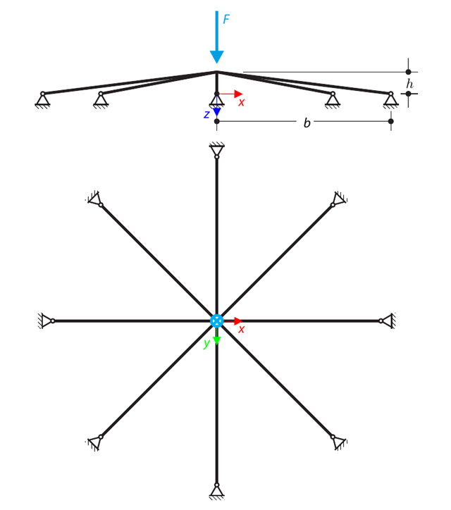
A symmetrical shallow structure is made of eight equal truss members, which are embedded into hinge supports. The structure is loaded by a concentrated force and alternatively by imposed nodal deformation over the critical limit point when the snap-through occurs. Imposed nodal deformation is used in RFEM 5 and RSTAB 8 to obtain the full equilibrium path of the snap-through. Vlastní tíha se v tomto příkladu nezohledňuje. Determine the relationship between the actual loading force and the deflection, considering large deformation analysis. Evaluate the load factor at the given deflections.
A spherical balloon membrane is filled with gas with atmospheric pressure and defined volume (these values are used for FE model definition only). Determine the overpressure inside the balloon due to the given isotropic membrane prestress. K tomu slouží přídavný modul RF-FORM-FINDING. Elastic deformations are neglected both in RF-FORM-FINDING and in the analytical solution; self-weight is also neglected in this example.
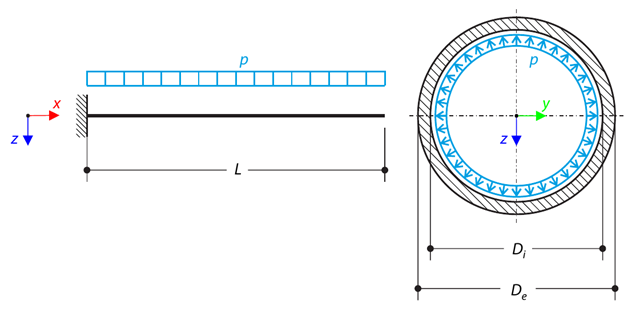
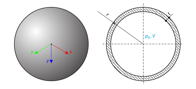
A pipe with a tubular cross-section is loaded by internal pressure. This internal pressure causes axial deformation of the pipe (the Bourdon effect). Stanovte axiální deformaci koncového bodu trubky.
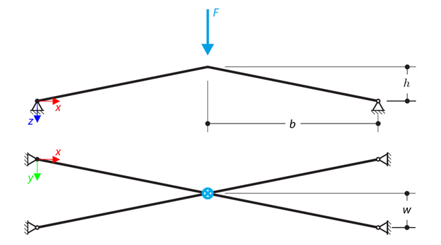
Konstrukce se skládá ze čtyř prutů, které jsou uloženy na kloubových podporách. The structure is loaded by a concentrated force and alternatively by imposed nodal deformation over the critical limit point, when snap-through occurs. Imposed nodal deformation is used in RFEM 5 and RSTAB 8 to obtain the full equilibrium path of the snap-through. The self-weight is neglected in this example. Determine the relationship between the actual loading force and the deflection, considering large deformation analysis. Evaluate the load factor at given deflections.
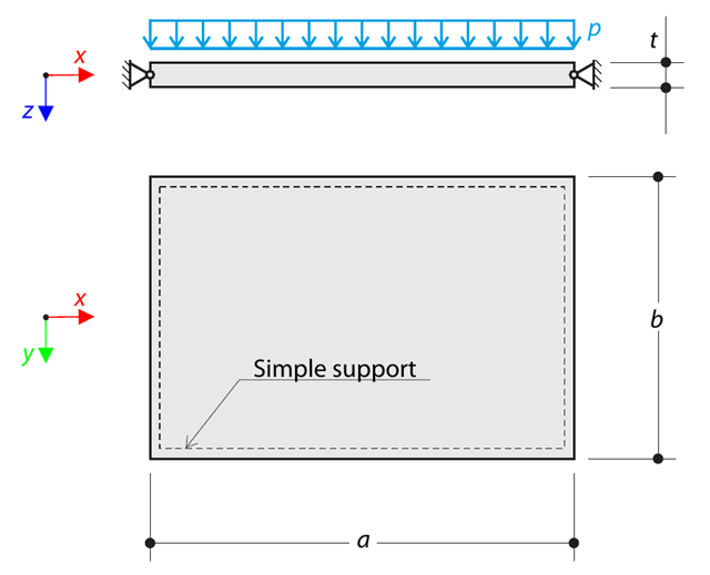
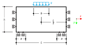
A thin rectangular orthotropic plate is simply supported and loaded by uniformly distributed pressure. The directions of axes x and y coincide with the principal directions. Maximální průhyb desky se stanoví bez zohlednění vlastní tíhy.
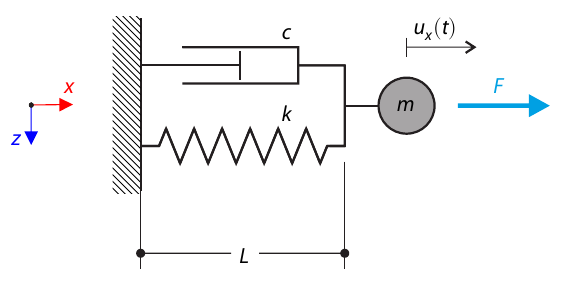
Jednohmotový systém s tlumičem je vystaven konstantní zatěžovací síle. Determine the deflection and velocity of the dashpot endpoint in the given test time.
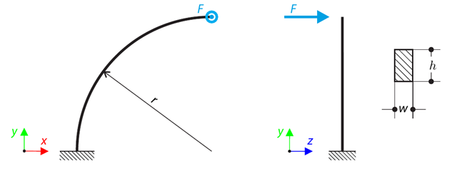
A quarter-circle beam with a rectangular cross-section is loaded by means of an out-of-plane force. This force causes a bending moment, torsional moment, and transverse force. Stanovíme celkový průhyb zakřiveného nosníku bez zohlednění vlastní tíhy.
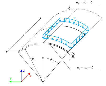
Modelujeme skořepinovou střešní konstrukci namáhanou tlakem, kde jsou rovné okraje volné, zatímco na zakřivených okrajích jsou posunuty osy y a z omezeny. Neglecting self‑weight, compute the maximum (absolute) vertical deflection, and compare the results with COMSOL Multiphysics 4.3.
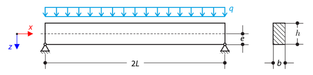
Kloubový nosník s obdélníkovým průřezem je namáhán rovnoměrným zatížením a vykazuje posun ve svislém směru vlivem excentricity. Considering the small deformation theory, neglecting the self‑weight, and assuming that the beam is made of isotropic elastic material, determine the maximum deflection.
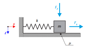
Jednoduchý oscilátor se skládá z tělesa o hmotnosti m (uvažuje se pouze ve směru osy x) a lineární pružiny s tuhostí k . The mass is embedded on a surface with Coulomb friction and is loaded by constant-in-time axial and transverse forces.
Dvoupodlažní rámová konstrukce o jednom poli je vystavena seizmickému zatížení. The modulus of elasticity and cross‑section of the frame beams are much larger than those of the columns, so the beams can be considered rigid. The elastic response spectrum is given by the standard SIA 261/1:2003. Neglecting self-weight and assuming the lumped masses are at the floor levels, determine the natural frequencies of the structure. For each frequency obtained, specify the standardized displacements of the floors as well as equivalent forces generated using the elastic response spectrum according to the standard SIA 261/1.2003.
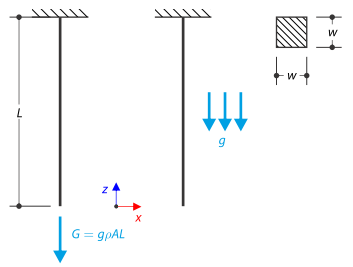
Tyč se čtvercovým průřezem je na svém horním konci vetknutá. The rod is loaded by self-weight. For comparison, the example is also modeled with the concentrated force load, the value of which is equal to the gravity. The aim of this verification example is to show the difference between these types of loading, although the total loading force is equal.
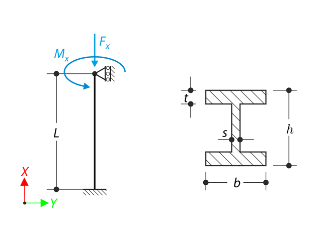
A member with the given boundary conditions is loaded by torsional moment and axial force. Neglecting its self-weight, determine the beam's maximum torsional deformation as well as its inner torsional moment, defined as the sum of a primary torsional moment and torsional moment caused by the normal force. Tyto hodnoty porovnáme při zohlednění nebo zanedbání vlivu normálové síly. The verification example is based on the example introduced by Gensichen and Lumpe.
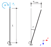
Uvažujeme tuhou lešenářskou trubku, která je ve spodní části fixně podepřena uzlovou podporou pro lešení a zatížena momentem i silou. Calculate the maximum deflection with consideration of initial slippage.
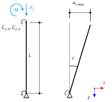
Uvažujeme tuhou lešenářskou trubku, která je ve spodní části fixně podepřena uzlovou podporou pro lešení a zatížena momentem i silou. Calculate the maximum radial deflection by exceeding the capacity of the scaffolding support.
Časová analýza konzoly (SDOF - systém s jedním stupněm volnosti), která je buzena periodickou funkcí. Vertical deformations and accelerations calculated with direct integration and modal analysis in RF‑/DYNAM Pro - Forced Vibrations are compared with the analytical solution.
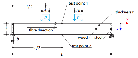
A timber beam reinforced by two steel plates at the ends is loaded by pressure. The wood fibers are parallel to the upper loaded side of the beam. Plastická plocha je popsána podle teorie plasticity Tsai-Wu.